Modular test & measurement
Reduce your debugging time
Connect your instruments, automate setup and investigate signals in one application. Modular Bench instruments and Control Hub help you spend less time managing the bench and more time solving the problem.
Instruments
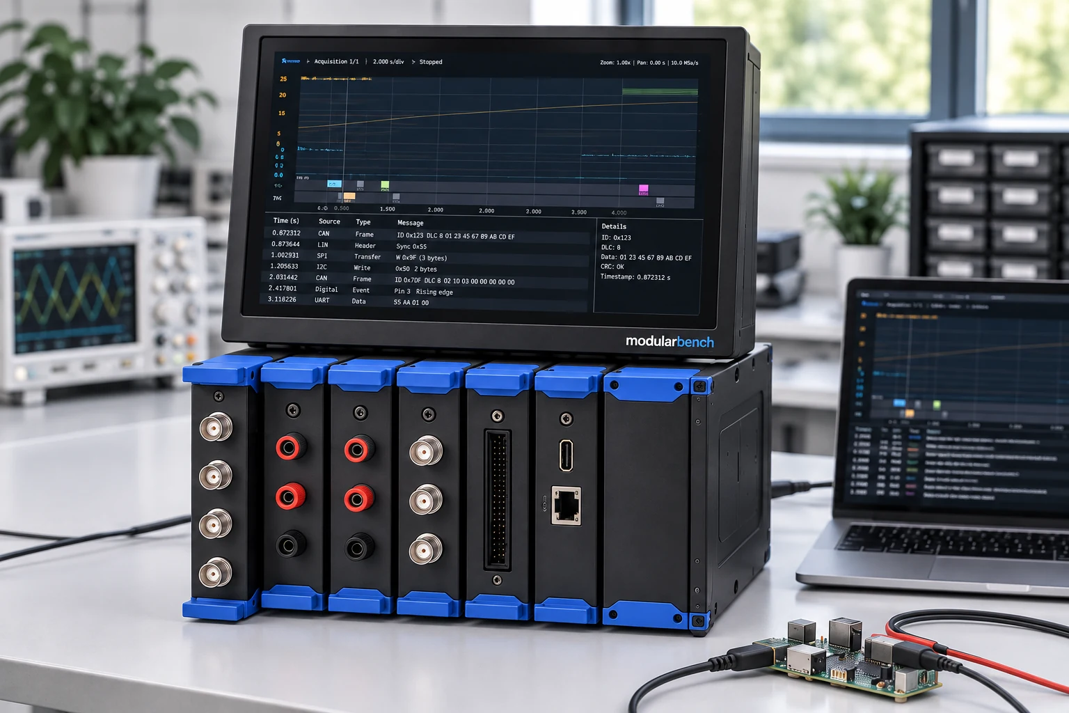
Use each instrument with a host computer, or mount several in the optional rack.
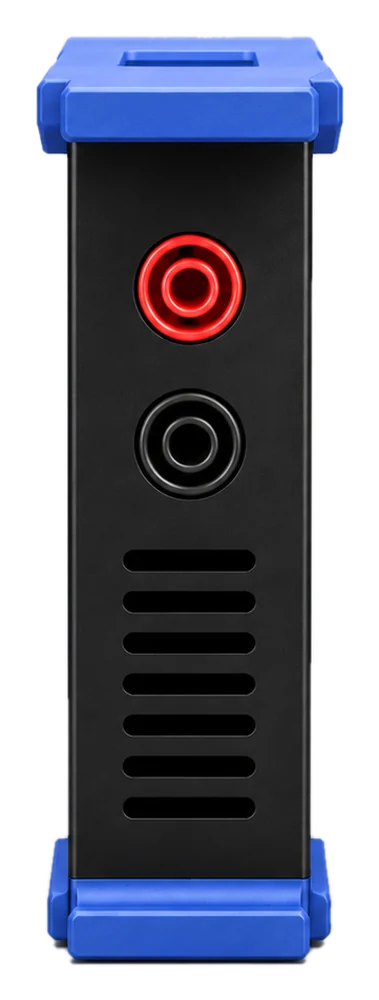
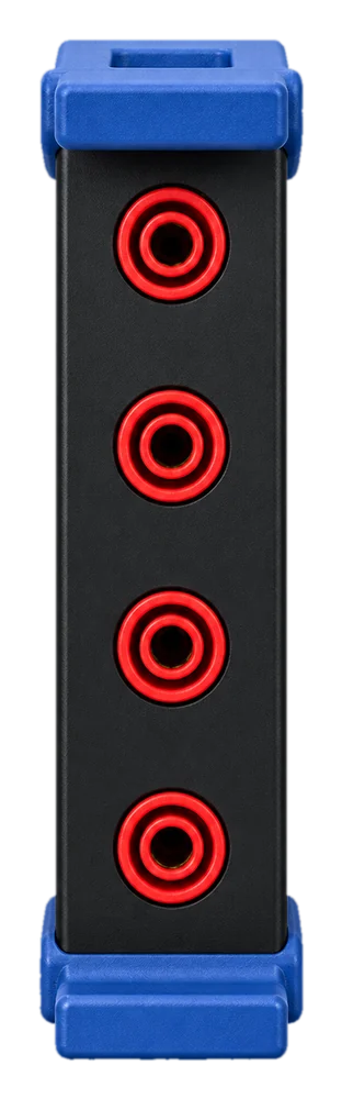
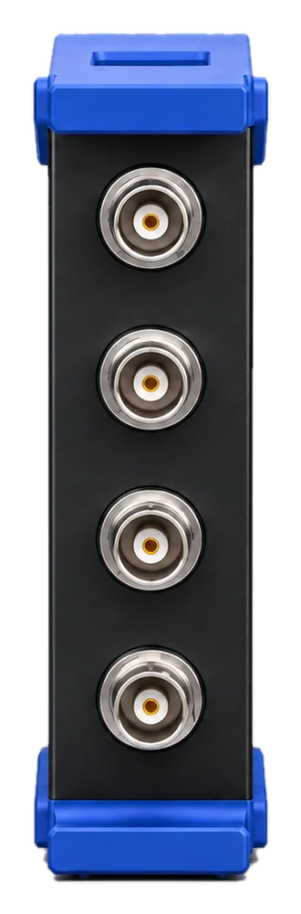
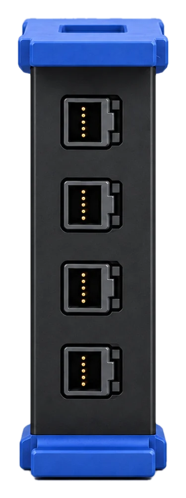
Arbitrary Waveform Generator
Same enclosure as the oscilloscope
4ch
Analog output channels
Pricing to be announced
DC Electronic Load
Same enclosure as the power supply
4modes
Constant current, voltage, resistance and power
Pricing to be announced
Source Measure Unit
Reference enclosure shown
4quadrant
Source and sink in both polarities
Pricing to be announced
Base system
Seven-slot rack
Rack frame, touchscreen and host computer with seven module positions.
Configure your lab
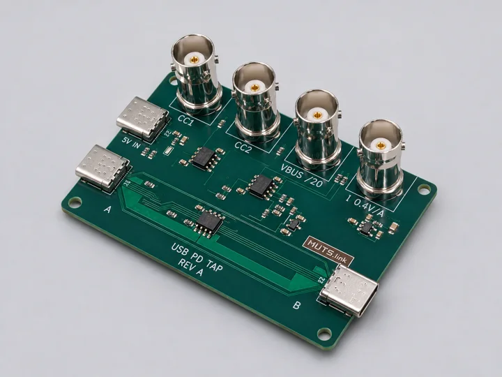
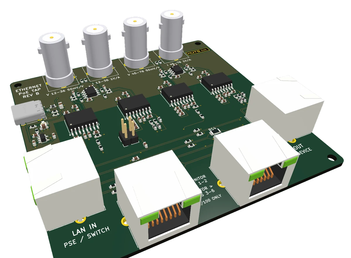
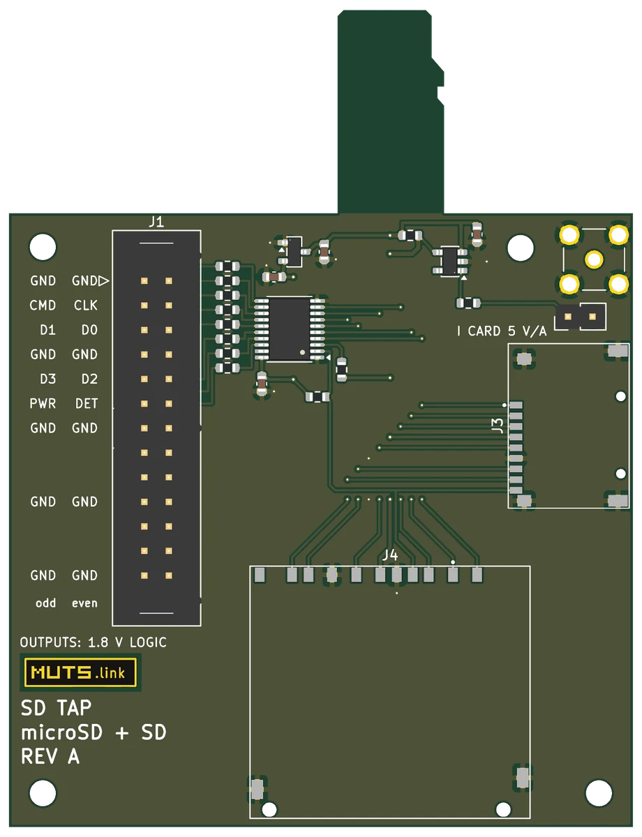
Test fixtures
External boards that connect instruments to USB-C, Ethernet/PoE and SD/microSD signals. No rack slot required.
Measurement benches
USB PD and PoE analyzers
Bench setups that use these fixtures: instrument connections, scaling and Control Hub captures.
View benches
Example workflow: USB PD analysis
USB PD bench detailsOpen a saved setup
Load the instrument inputs, probe scaling and run settings.
Run the measurement
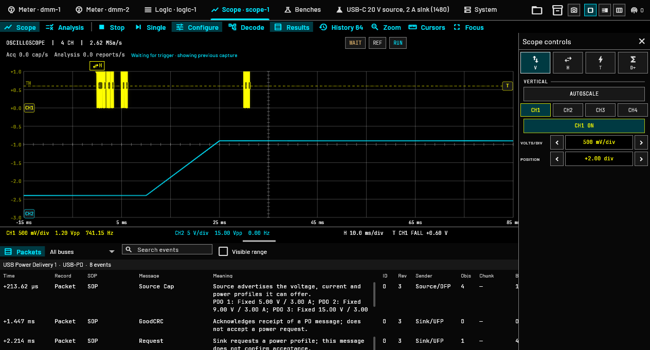
Record PD messages alongside voltage, current and power.
Review the recorded result
Inspect the negotiation, measured values and checks from the saved run.
Observing a 20 V / 2 A USB PD negotiation in Control Hub, using simulated instrument inputs.
Desktop, browser or tablet
Run Control Hub as a desktop application, or use a browser on a computer or tablet. Operate locally or connect remotely to your lab.
Connection requirements
The desktop application runs on the instrument host. Browser and tablet access connect to that host over the network. Access from outside the lab requires an appropriate remote-network connection.
AI-assisted instrument control
Describe the task in plain language. Inspect the assistant’s actions and continue working with the instrument controls.
CAN DECODING EXAMPLE
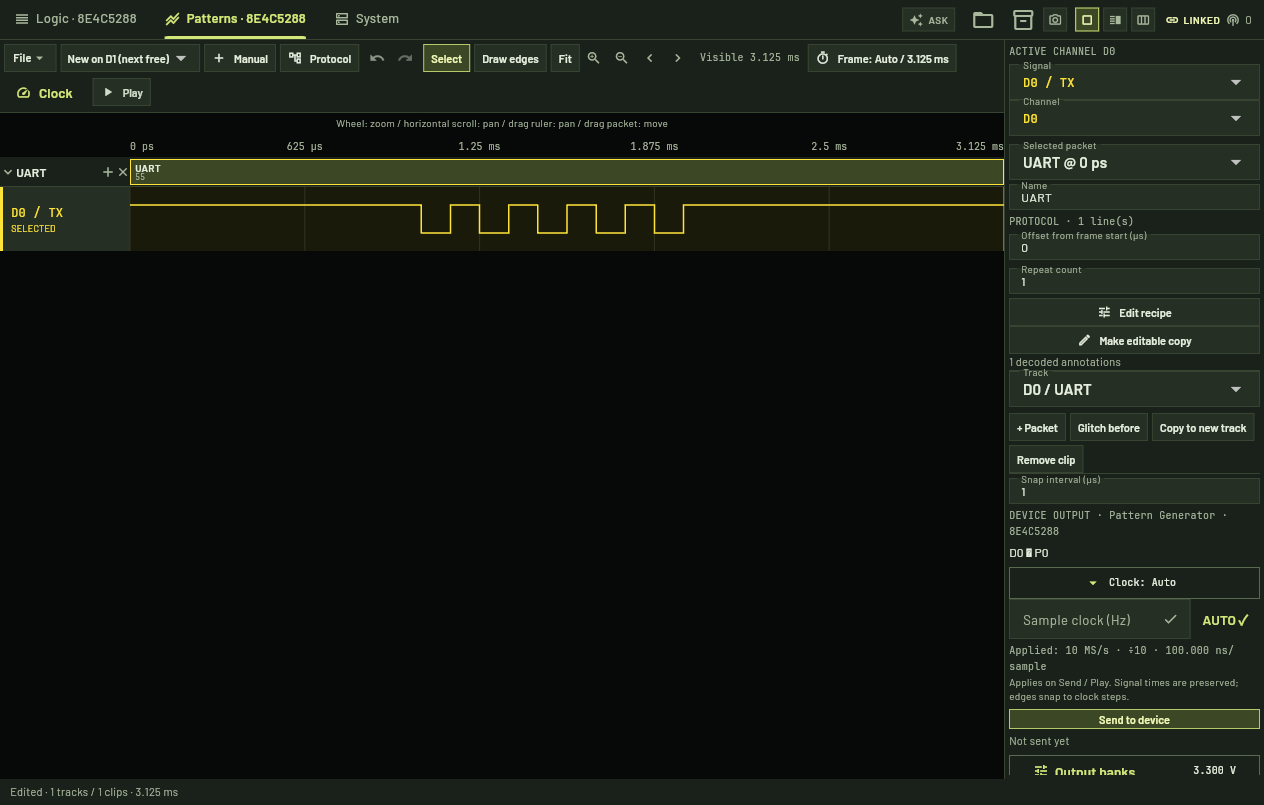
“Do any logic analyzer signals carry CAN at 500 kbit/s?”
- 01
Inspect the channels
Search all 16 logic inputs.
- 02
Check the decoding
Compare frames at 500 kbit/s with other bit rates.
- 03
Apply the decoder
CAN found on D1. Decoder left applied for inspection.
Example session with simulated CAN signals
Assistant connection
The assistant requires a configured model connection; model hosting and provider terms are separate from instrument software access.
Existing equipment examples
Connect supported lab equipment alongside Modular Bench devices in Control Hub. Instrument controls and available measurements follow the connected model.
Digital multimeter
HP 34401A
Source measure unitAgilent / Keysight B2900
OscilloscopeMicsig MHO
Spectrum analyzerRigol DSA800
Selected driver support. Brand and model names identify third-party equipment; no affiliation or endorsement is implied.
Rack · Touchscreen · Host computer
Seven-slot base system
Choose up to seven instrument modules for the desktop rack, or use modules individually. The touchscreen and host computer provide a shared interface.
Base system details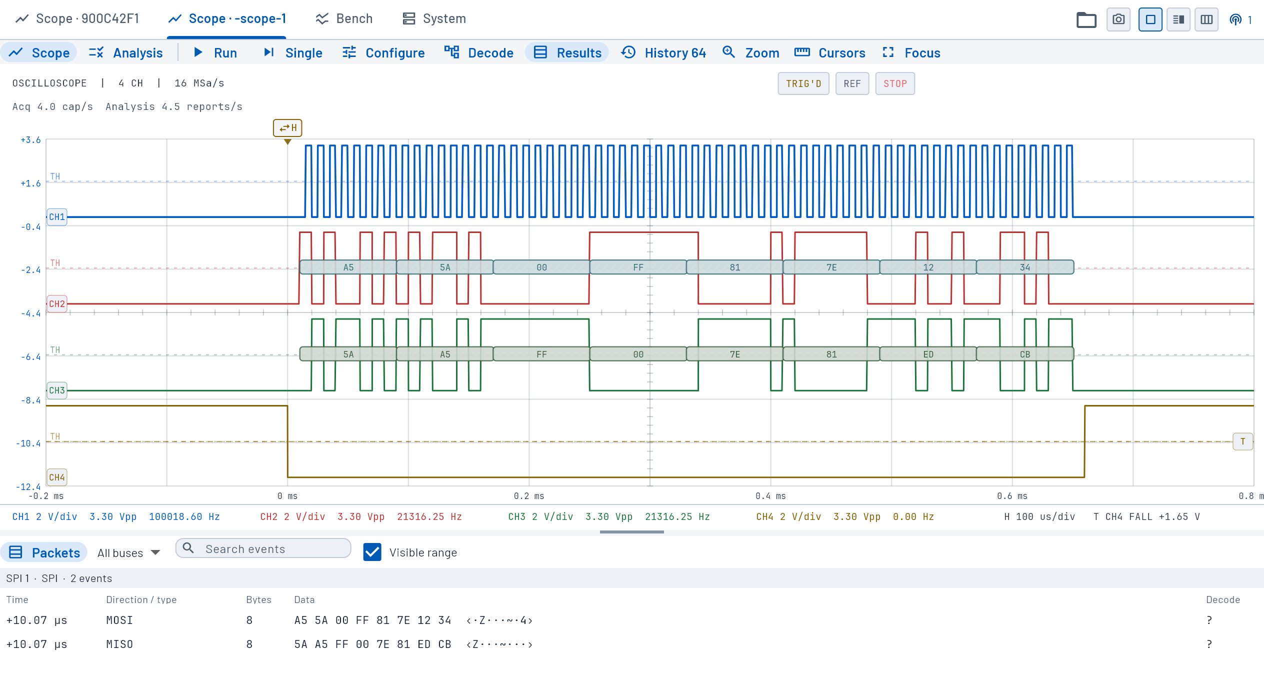 Control Hub
01LOGIC
02SCOPE
03AWG
04POWER
05METER
06EMPTY
07EMPTY
Host computerBASE SYSTEM
Hardware triggering
Signal conditions, protocol events and timing controls.
Trigger types ↗Protocol support
Decoder interfaces, pattern generation and hardware triggering.
Support matrix ↗Hardware platform
Module interfaces, source releases and hardware specifications.
Platform details ↗