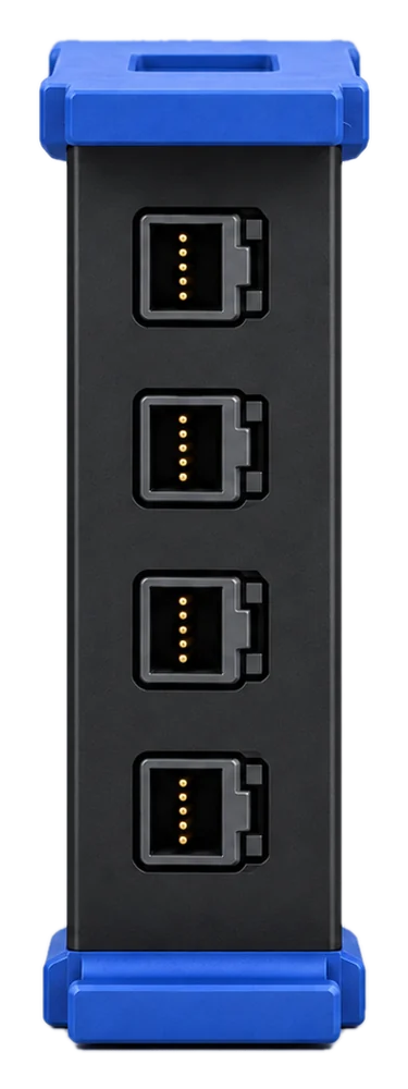
Logic Analyser
MB-LA16
Instrument module · MB-SCOPE14
Four common-ground analog inputs with 14-bit ADCs. Capture at 80 MS/s per channel with four inputs, 160 MS/s with two, or 320 MS/s on CH1. Bandwidth is 20 MHz or 60 MHz, depending on mode.
SKU MB-SCOPE14
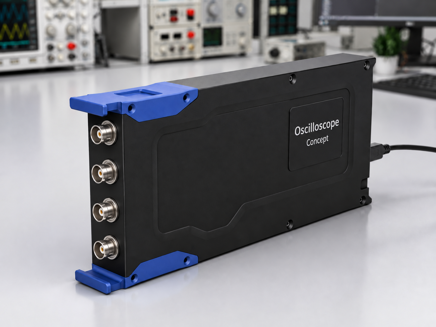
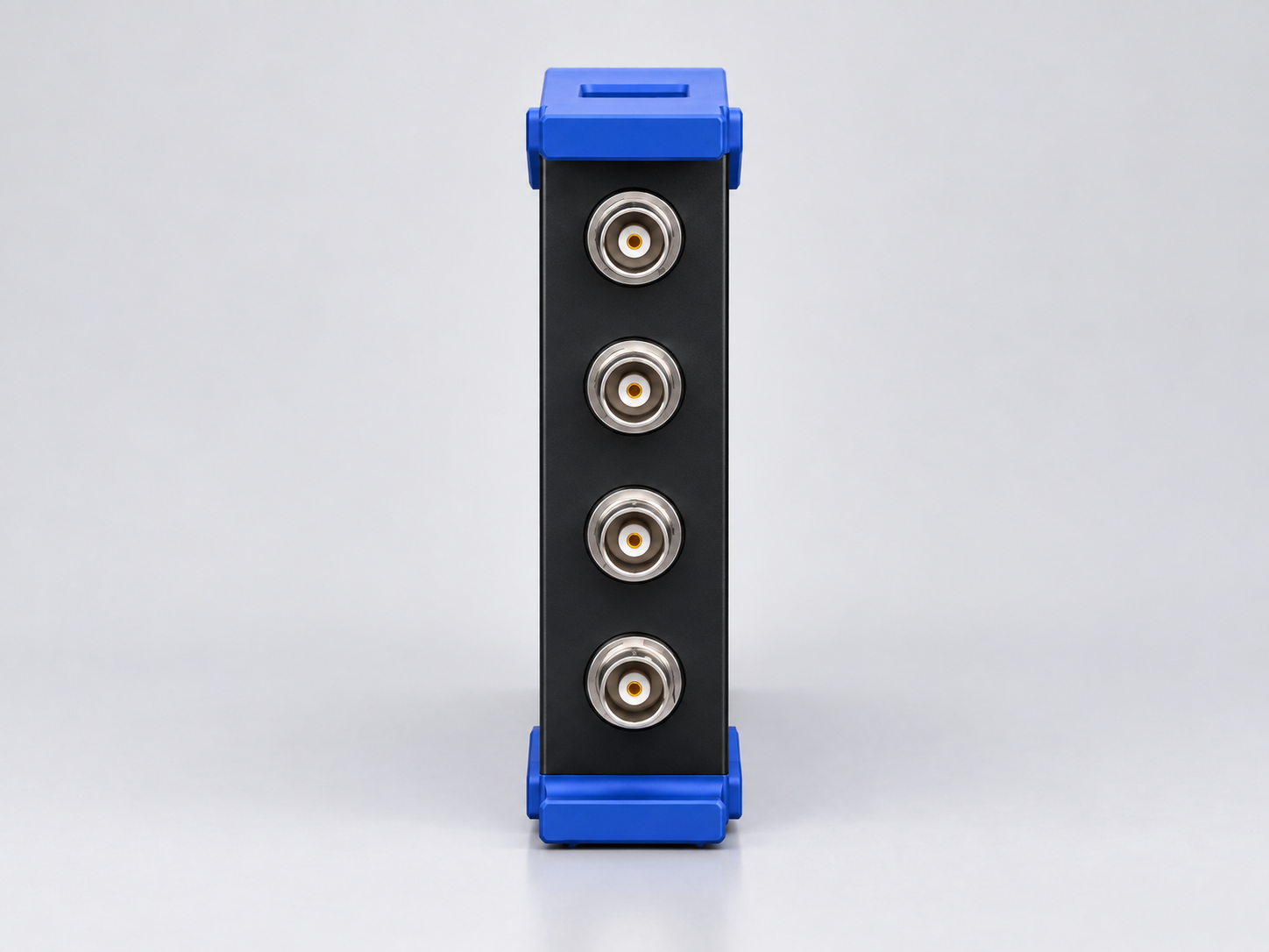
1 / 2Bench view
Software · Firmware · Gateware
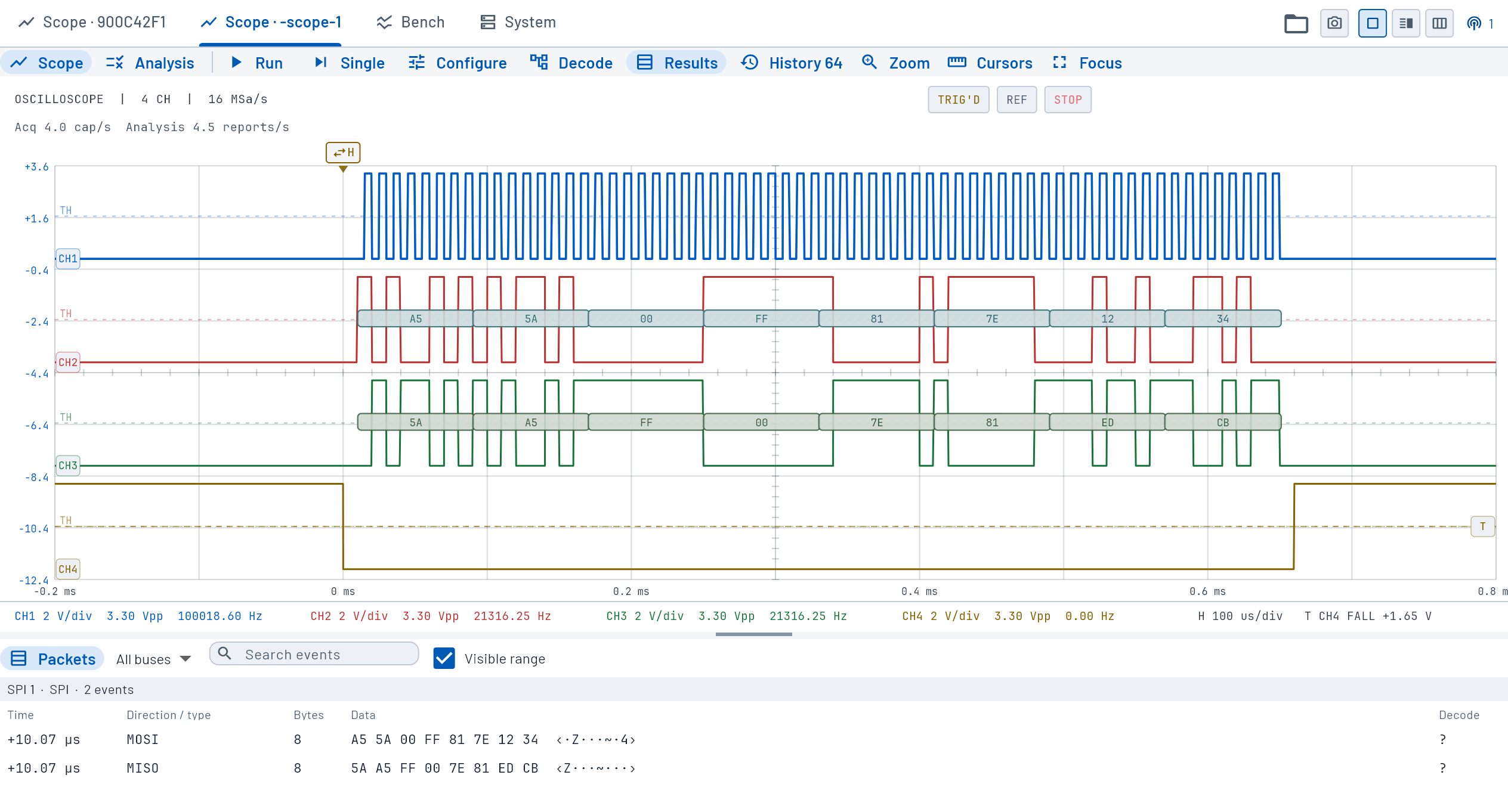
Set trigger conditions in Control Hub, then inspect waveforms, measurements and decoded protocol traffic in the same capture.
View trigger typesBlock diagram
Four inputs feed a 14-bit ADC running at 80 to 320 MS/s depending on channel allocation. The FPGA acquisition engine buffers samples in DDR memory before the MCU streams them over USB-C 3.0 or gigabit Ethernet.
BLOCK-LEVEL · NOT A SCHEMATIC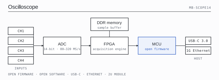
Input ranges, acquisition modes and operating conditions.
Higher-rate modes use ADC interleaving: CH1 + CH2 at 160 MS/s per channel, or CH1 at 320 MS/s.
| Active inputs | Real-time sample rate | Bandwidth / condition |
|---|---|---|
| 4 channels · CH1–CH4 | 80 MS/s per channel | 20 MHz bandwidth |
| 2 channels · CH1 + CH2 | 160 MS/s per channel | 60 MHz bandwidth; interleaved |
| 1 channel · CH1 | 320 MS/s | 60 MHz bandwidth; interleaved |
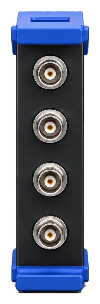
Four common-ground BNC inputs. Ranges are input-referred peak values, not volts per division.
| Parameter | Specification | Conditions |
|---|---|---|
| Input channels / connectors | 4 × BNC | Common ground; no galvanic isolation |
| ADC resolution | 14 bit | Hardware definition; not a claim of 14 effective bits |
| High-impedance input | 1 MΩ ±1%; 10–16 pF | complete BNC, PCB and enclosure |
| Terminated input | 50 Ω ±2% | selectable termination |
| Coupling | AC / DC in 1 MΩ; DC only in 50 Ω | 50 Ω mode forces DC coupling |
| 1 MΩ input ranges | ±5, 10, 20, 50, 100, 200, 500 mV; ±1, 2, 5, 10, 20 V | 1–2–5 sequence; ±R means 2R peak-to-peak |
| 50 Ω input ranges | Same sequence through ±5 V | Normal measurement range, not a fault rating |
| AC coupling corner | ≤2 Hz | 1 MΩ mode |
Accuracy and signal quality after calibration.
| Parameter | Specification | Conditions |
|---|---|---|
| DC–1 kHz accuracy, 20–30 °C | ±1.0% of reading ±0.10% of range | After calibration |
| DC–1 kHz accuracy, 10–40 °C | ±2.0% of reading ±0.25% of range | After calibration |
| Offset span: ±5 / 10 / 20 mV ranges | ±25 mV | Signal plus offset must stay within the input range |
| Offset span: ±50 / 100 / 200 mV ranges | ±250 mV | Input offset span |
| Offset span: ±0.5 / 1 / 2 V ranges | ±2.5 V | Input offset span |
| Offset span: ±5 / 10 / 20 V ranges | ±20 V | Input offset span |
| RMS noise, ±5 mV range | ≤15 µV at 20 MHz; ≤25 µV at 60 MHz | grounded 1 MΩ or terminated 50 Ω input, no averaging |
| SINAD at 1 MHz | ≥48 dB on ±5 / 10 / 20 mV; ≥60 dB on other ranges | 90%-range sine, any acquisition mode |
| SINAD at 60 MHz | ≥40 dB on ±5 / 10 / 20 mV; ≥48 dB on other ranges | 90%-range sine, interleaved modes |
| SFDR | ≥60 dBc at 1 MHz; ≥50 dBc at 60 MHz | 90%-range sine, calibrated; 60 MHz in interleaved modes |
| Passband flatness | ±0.50 dB through 0.75 × bandwidth | DC coupled, from 10 Hz or 10 × AC corner, whichever is higher |
| 10–90% rise time | ≤25 ns at 20 MHz; ≤8.5 ns at 60 MHz | Mode-dependent bandwidth |
| Channel isolation | ≥60 dB in 4-channel mode; ≥54 dB in 2-channel mode | Through mode bandwidth; same-range grounded victim, 90%-range aggressor |
Rates above are per displayed input. Record length, transport throughput and acquisition firmware are separate specifications.
| Parameter | Specification | Conditions |
|---|---|---|
| Real-time acquisition | 80 / 160 / 320 MS/s | See channel allocation above |
| Sampling-clock aperture jitter | ≤0.66 ps RMS | Combined sampling jitter; separate from trigger jitter |
| Residual ADC-path skew | ≤3 ps after calibration | Interleaved ADC paths; separate from channel-to-channel skew |
Control Hub provides waveform display, analysis and instrument control.
| Parameter | Specification | Conditions |
|---|---|---|
| Host application | Control Hub | Shared instrument application |
| Software access | All features across devices; no paid unlocks | Open-source software, firmware and gateware; licence details accompany source releases |
USB-C and Ethernet connect the instrument to its host.
| Parameter | Specification | Conditions |
|---|---|---|
| Host interfaces | USB-C / Ethernet | Host control and data transfer |
| Power input | USB-C | Power input |
Input grounding, measurement conditions and calibration records.
| Parameter | Specification | Conditions |
|---|---|---|
| Isolation / measurement category | Common ground; no CAT rating claimed | No mains-safety or galvanic-isolation approval |
| Measurement conditions | 10–40 °C after 20 minutes warm-up | Narrower conditions apply to some accuracy limits |
| Calibration / test documentation | Per-device reports through the customer account | Account sign-in required |
Instrument module format.
| Parameter | Specification | Conditions |
|---|---|---|
| Module format | 2U | Modular Bench format |
| Parameter | Specification | Detail |
|---|---|---|
| Module format | 2U | Modular Bench format |
| Rack capacity | 7 module positions | Modular Bench format |
| User interface | Shared touchscreen | Modular Bench format |
| Control interfaces | USB-C / Ethernet | Modular Bench format |
| Power input | USB-C | Modular Bench format |
System interfaces, software features and equipment records.
Control Hub
Four-channel waveform display with SPI decoding, packet results and channel controls.
MB-LA16
MB-PS240
MB-DMM45
MB-AWG4
MB-LOAD
MB-SMU