Instrument features
Software &
system features
Shared software for all devices
FPGA hardware triggering from edges to protocol frames and multi-step sequences, 137 protocol decoders, digital pattern generation and capture analysis. Software, firmware and gateware are open source.
Trigger types01 / Hardware triggering
Hardware trigger types
Every trigger is evaluated in the FPGA at 700 MS/s, before capture decimation, so the decision does not depend on the host. Basic triggers cover edges, logic patterns and the external input. Advanced triggers add time qualification, two-input timing and protocol frames; sequences chain up to four steps.
Basic
Edge, logic pattern and the MCX external input. The usual starting points, with the same 1.43 ns resolution as every other type.
EDGE · PATTERN · EXTERNALAdvanced timing
Pulse width, timeout, Nth edge, A-to-B delay and setup/hold violations. Time conditions take below, above, inside or outside limits; holdoff suppresses re-triggering for up to 24 s.
PULSE · TIMEOUT · NTH · DELAY · SETUP/HOLDProtocol
Frame, field and error conditions decoded in the FPGA: select a protocol, then match the frame, field or error that matters to your capture.
CAN · CAN FD · UART · LIN · FLEXRAY · USB PD · SENT · T1SSequence
Up to four signal steps in a row; one step arms the next and the last triggers. Time-outs restart the sequence.
STEP 1 → 2 → 3 → 4Basic
Advanced timing
Protocol
Sequence
Pulse-width trigger
Trigger on high or low pulses with widths below, above, inside or outside the selected time limits.
D0 · High pulse < 20 ns
The trigger fires at the end of the qualifying pulse.
| Trigger | Class | Settings | Fires |
|---|---|---|---|
| Edge | Basic | Input; rising, falling or either edge | At the edge |
| Pattern | Basic | H / L / don’t care per input; qualifier: enters, exits, lasts (time condition), holds longer than t | Where the pattern starts, ends or meets its time condition |
| External input | Basic | MCX trigger input; rising, falling or either edge; independent threshold | At the external edge; routes to capture or generator start |
| Pulse width | Advanced | Input; high or low pulse; width < t, > t, inside or outside t1..t2 | At the edge that ends a qualifying pulse |
| Timeout | Advanced | Input; level after the edge (high, low, either); time t | t after the edge if the line still holds the level |
| Nth edge | Advanced | Input; edge; idle time; N = 1..65535 | At the Nth edge of a burst that follows the idle time |
| A → B delay | Advanced | Input A + edge; input B + edge; condition on the A-to-B time | At the B edge |
| Setup / hold | Advanced | Data input; clock input + edge; setup time, hold time; check either or both | At the clock edge (setup) or the data edge (hold) that violates the window |
| Holdoff | Advanced | 0–24 s in 5.7 ns steps; applies to every type | Suppresses re-triggering until the holdoff has elapsed |
| Protocol | Trigger conditions |
|---|---|
| CAN | Valid frame filtered by identifier, frame type and masked data bytes; CRC, missing ACK, stuff and form errors; active error flag. |
| CAN FD | As CAN, with the FD CRC lengths, fixed-stuff and stuff-count errors and the FD form bits. |
| UART / USART | A value or a sequence of up to 16 characters; parity and framing errors, break, idle timeout. |
| LIN | Break, header, identifier with mask, identifier plus data bytes; parity, sync, checksum and framing errors; wake-up. |
| FlexRay | Valid frame with filters; frame start; header fields before the frame ends; header-CRC, frame-CRC and coding errors; CAS/MTS symbol; wake-up. |
| USB Power Delivery | Packet with filters; ordered sets (SOP, Hard Reset, Cable Reset); fields of a running packet; CRC, EOP, 4B5B code and framing errors. |
| SENT | Fast-channel frame with status/data filter; slow-channel message with ID/data filter; CRC, calibration, nibble and pause errors; Nth occurrence. |
| 10BASE-T1S | Frame with filters and length limits; frame start; fields of a running frame; FCS, end-delimiter, coding and length errors. |
| I2C, I3C, MDIO, SPI, USB low/full speed, encoder | Address, data and error conditions per protocol specification. |
| JTAG, Modbus RTU, 1-Wire | Instruction, register and error conditions per protocol specification. |
Trigger sequences
Up to four signal trigger steps in a row, each with its own inputs and settings. One step arms the next; the last step triggers the capture.
- Any of the signal trigger types can be a step, with its own input lines.
- A step’s deciding sample must follow the previous step’s by at least 80 ns.
- An optional time-out per step restarts the sequence from step 1; restarts are counted and reported.
- The trigger marker, holdoff and pre-trigger allocation belong to the last step.
- Protocol steps are not part of the main-image sequence; a single protocol trigger uses its own image.
Trigger holdoff
0–24 s between accepted triggers, in 5.7 ns steps. Forced and arm triggers are not held off.
LA16 and scope
Control Hub uses a shared trigger interface. Select the source, condition and pre-trigger history for the connected instrument.
Decision point
Protocol triggers decide at the end of the frame or field they match. Set enough pre-trigger history to keep the start of the transaction in the record.
LA16 trigger timing
The signal engine evaluates inputs at 700 MS/s before capture decimation. This is the trigger-engine rate; input frontend bandwidth is specified separately. Delay and setup/hold modes check the first relevant edges in each four-sample cycle. Timeout and burst-idle settings require at least four samples. Multi-line patterns can be affected by input skew of up to about 3 ns between lines.
Protocol modes use dedicated FPGA images selected by the driver; these are not all simultaneous trigger engines.
02 / Protocol analysis
Protocol decoding
Decoded addresses, data and errors are displayed alongside the waveform, on every device, with no separate protocol licences. Search the matrix for a protocol or a device-specific decoder.
decoders
Decode I²C, SPI, UART, CAN, USB PD, Modbus and more. Search below for the protocols you use.
137 protocols shown
| Protocol | Interface | Decode supported | Decoder source | Pattern generation supported | Hardware triggering supported |
|---|---|---|---|---|---|
| 1-WireInputs: 1 | Digital / analog | Yes | Native | Yes | Yes |
| 10BASE-T1L (PAM3)Inputs: the pair's two legs | Analog | Yes | Native | No | No |
| 10BASE-T1SInputs: positive, negative | Digital / analog | Yes | Native | Yes | Yes |
| 24xx EEPROM24xx series I²C EEPROM commands | Digital / analog | Yes | Library | No | No |
| 93xx EEPROM93xx series Microwire EEPROM commands | Digital / analog | Yes | Library | No | No |
| 100BASE-T1 (PAM3)Inputs: the pair's two legs | Analog | Yes | Native | No | No |
| AC'97Audio Codec ’97 AC-Link between controller and codec | Digital / analog | Yes | Library | No | No |
| AD5626Analog Devices AD5626 12-bit DAC (SPI) | Digital / analog | Yes | Library | No | No |
| AD7910 / AD7920Analog Devices AD79x0 SPI ADC | Digital / analog | Yes | Library | No | No |
| ADE77xxAnalog Devices ADE77xx energy-metering IC (SPI) | Digital / analog | Yes | Library | No | No |
| ADF4350 / ADF4351Analog Devices ADF435x wideband synthesizer registers | Digital / analog | Yes | Library | No | No |
| ADNS-5020Avago ADNS-5020 optical mouse sensor | Digital / analog | Yes | Library | No | No |
| ADXL345Analog Devices ADXL345 three-axis accelerometer | Digital / analog | Yes | Library | No | No |
| AM230x / DHTxxAosong AM230x and DHTxx humidity and temperature sensors | Digital / analog | Yes | Library | No | No |
| Amulet ASCIIAmulet LCD module ASCII command protocol | Digital / analog | Yes | Library | No | No |
| ARM ETMv3ARM Embedded Trace Macrocell v3 instruction trace | Digital / analog | Yes | Library | No | No |
| ARM ITMARM Instrumentation Trace Macrocell | Digital / analog | Yes | Library | No | No |
| ARM TPIUARM Trace Port Interface Unit framing | Digital / analog | Yes | Library | No | No |
| ATSHA204AMicrochip ATSHA204A crypto authentication (I²C) | Digital / analog | Yes | Library | No | No |
| AUDRenesas / Hitachi Advanced User Debugger trace | Digital / analog | Yes | Library | No | No |
| AVR ISPAVR in-system programming commands (SPI) | Digital / analog | Yes | Library | No | No |
| AVR PDIAVR Program and Debug Interface | Digital / analog | Yes | Library | No | No |
| BiSS-CInputs: MA, SLO | Digital / analog | Yes | Native | Yes | No |
| Bit-rate guessBit-rate / baud-rate estimation | Digital / analog | Yes | Library | No | No |
| CANInputs: CAN (or CAN_H / CAN_L analog) | Digital / analog | Yes | Native | Yes | Yes |
| CAN FDInputs: CAN | Digital / analog | Yes | Native | Yes | Yes |
| CC1101TI CC1101 sub-1 GHz transceiver registers (SPI) | Digital / analog | Yes | Library | No | No |
| CFP100 Gbit/s CFP optical module management (MDIO) | Digital / analog | Yes | Library | No | No |
| cJTAGCompact JTAG, IEEE 1149.7 | Digital / analog | Yes | Library | No | No |
| CounterEdge and pulse counter | Digital / analog | Yes | Library | No | No |
| DALIInputs: 1 | Digital / analog | Yes | Native | Yes | No |
| DCF77DCF77 time-signal frames | Digital / analog | Yes | Library | No | No |
| Digital caliperDigital caliper serial measurement output | Digital / analog | Yes | Library | No | No |
| DMX512Inputs: 1 | Digital / analog | Yes | Native | Yes | No |
| DS28EA00Maxim DS28EA00 1-Wire digital thermometer | Digital / analog | Yes | Library | No | No |
| DS1307Dallas DS1307 real-time clock (I²C) | Digital / analog | Yes | Library | No | No |
| DS2408Maxim DS2408 1-Wire eight-channel switch | Digital / analog | Yes | Library | No | No |
| DS2432 / DS2433Maxim DS243x 1-Wire EEPROM | Digital / analog | Yes | Library | No | No |
| DSIDigital Serial Interface lighting control | Digital / analog | Yes | Library | No | No |
| EDIDExtended Display Identification Data (I²C) | Digital / analog | Yes | Library | No | No |
| EM4100EM4100 125 kHz RFID tag data | Digital / analog | Yes | Library | No | No |
| EM4305EM4305 125 kHz RFID commands | Digital / analog | Yes | Library | No | No |
| ENC28J60Microchip ENC28J60 Ethernet controller (SPI) | Digital / analog | Yes | Library | No | No |
| FlexRayInputs: 1 | Digital / analog | Yes | Native | Yes | Yes |
| Gray codeGray-code and rotary encoder | Digital / analog | Yes | Library | No | No |
| HDCPHDCP over HDMI (I²C) | Digital / analog | Yes | Library | No | No |
| HDMI-CECInputs: 1 | Digital / analog | Yes | Native | Yes | No |
| I2CInputs: SCL, SDA | Digital / analog | Yes | Native | Yes | Yes |
| I2C demuxI²C demultiplexer by slave address | Digital / analog | Yes | Library | No | No |
| I2C filterI²C filter by slave address | Digital / analog | Yes | Library | No | No |
| I2SInputs: SCK, WS, SD | Digital / analog | Yes | Native | Yes | No |
| I3C (SDR, HDR-DDR)Inputs: SCL, SDA | Digital / analog | Yes | Native | Yes | Yes |
| IEEE-488 / GPIBIEEE-488 (GPIB, HP-IB) bus | Digital / analog | Yes | Library | No | No |
| IR remote (IRMP)Infrared remote, IRMP multi-protocol | Digital / analog | Yes | Library | No | No |
| IR remote (NEC, extended NEC, RC-5, RC-5X)Inputs: 1 | Digital / analog | Yes | Native | Yes | No |
| IR remote (RC-6)Infrared remote, RC-6 | Digital / analog | Yes | Library | No | No |
| IR remote (SIRC)Infrared remote, Sony SIRC | Digital / analog | Yes | Library | No | No |
| JitterJitter between two signals | Digital / analog | Yes | Library | No | No |
| JTAGInputs: TCK, TMS, TDI, TDO (+ TRST) | Digital / analog | Yes | Native | Yes | Yes |
| LFASTNXP LFAST high-speed serial link | Digital / analog | Yes | Library | No | No |
| LINInputs: 1 | Digital / analog | Yes | Native | Yes | Yes |
| LM75LM75 temperature sensor (I²C) | Digital / analog | Yes | Library | No | No |
| LPCLow Pin Count bus | Digital / analog | Yes | Library | No | No |
| LTC26x7Linear Technology LTC2607 / 2617 / 2627 DAC | Digital / analog | Yes | Library | No | No |
| LTC2421 / LTC2422Linear Technology LTC242x ADC | Digital / analog | Yes | Library | No | No |
| ManchesterInputs: 1 | Digital / analog | Yes | Native | Yes | No |
| Maple busSEGA Dreamcast Maple peripheral bus | Digital / analog | Yes | Library | No | No |
| MAX7219 / MAX7221Maxim MAX72xx LED display driver | Digital / analog | Yes | Library | No | No |
| MCP230xxMicrochip MCP230xx I/O expander (I²C) | Digital / analog | Yes | Library | No | No |
| MCS-48Intel MCS-48 external memory access | Digital / analog | Yes | Library | No | No |
| MDIOInputs: MDC, MDIO | Digital / analog | Yes | Native | Yes | Yes |
| MicrowireMicrowire three-wire serial bus | Digital / analog | Yes | Library | No | No |
| MIDIInputs: 1 | Digital / analog | Yes | Native | Yes | No |
| MillerMiller encoding (ISO 14443) | Digital / analog | Yes | Library | No | No |
| MIPS EJTAGMIPS EJTAG debug over JTAG | Digital / analog | Yes | Library | No | No |
| MLX90614Melexis MLX90614 infrared thermometer | Digital / analog | Yes | Library | No | No |
| Modbus RTUInputs: 1 | Digital / analog | Yes | Native | Yes | Yes |
| MorseMorse code | Digital / analog | Yes | Library | No | No |
| MRF24J40Microchip MRF24J40 IEEE 802.15.4 transceiver | Digital / analog | Yes | Library | No | No |
| MXC6225XUMEMSIC MXC6225XU accelerometer | Digital / analog | Yes | Library | No | No |
| NES gamepadNintendo NES gamepad shift register | Digital / analog | Yes | Library | No | No |
| nRF24L01(+)Nordic nRF24L01 2.4 GHz transceiver (SPI) | Digital / analog | Yes | Library | No | No |
| nRF905Nordic nRF905 sub-1 GHz transceiver (SPI) | Digital / analog | Yes | Library | No | No |
| Numbers and stateNumbers and state from parallel data | Digital / analog | Yes | Library | No | No |
| OOKOn-off keying demodulated data | Digital / analog | Yes | Library | No | No |
| OOK visualisationOOK pulse visualisation | Digital / analog | Yes | Library | No | No |
| Oregon ScientificOregon Scientific weather sensors (OOK) | Digital / analog | Yes | Library | No | No |
| PAN1321Panasonic PAN1321 Bluetooth module (UART) | Digital / analog | Yes | Library | No | No |
| Parallel busInputs: clock + up to 16 data + enable | Digital / analog | Yes | Native | Yes | No |
| PCA9571NXP PCA9571 I/O expander (I²C) | Digital / analog | Yes | Library | No | No |
| PJDLPJON data link layer | Digital / analog | Yes | Library | No | No |
| PJONPJON network protocol | Digital / analog | Yes | Library | No | No |
| PS/2Inputs: CLK, DATA | Digital / analog | Yes | Native | Yes | No |
| PWMInputs: 1 | Digital / analog | Yes | Native | Yes | No |
| QiQi wireless charging communication | Digital / analog | Yes | Library | No | No |
| RC encoderPT2262 / HX2262 remote-control encoder | Digital / analog | Yes | Library | No | No |
| RFM12HopeRF RFM12 transceiver (SPI) | Digital / analog | Yes | Library | No | No |
| RGB LED (SPI)SPI-driven RGB LED strings | Digital / analog | Yes | Library | No | No |
| RTC-8564Epson RTC-8564 real-time clock (I²C) | Digital / analog | Yes | Library | No | No |
| S.BUSFutaba S.BUS RC servo bus | Digital / analog | Yes | Library | No | No |
| S/PDIFInputs: 1 | Digital / analog | Yes | Native | Yes | No |
| SAE J1850 VPWSAE J1850 variable pulse width (OBD-II) | Digital / analog | Yes | Library | No | No |
| SD card (native 1 / 4 bit)Inputs: CLK, CMD, DAT0..3 | Digital / analog | Yes | Native | Yes | No |
| SD card (SPI mode)SD card SPI mode | Digital / analog | Yes | Library | No | No |
| SDA2506Siemens SDA2506 EEPROM | Digital / analog | Yes | Library | No | No |
| SDQApple SDQ single-wire bus | Digital / analog | Yes | Library | No | No |
| SENTInputs: 1 | Digital / analog | Yes | Native | Yes | Yes |
| Seven-segment displaySeven-segment display segments to digits | Digital / analog | Yes | Library | No | No |
| Signature analysisSignature analysis | Digital / analog | Yes | Library | No | No |
| SIPISIPI serial interface | Digital / analog | Yes | Library | No | No |
| SLE 44xxSLE 4418 / 4428 / 4432 / 4442 memory cards | Digital / analog | Yes | Library | No | No |
| SPIInputs: SCLK, MOSI, MISO, CS | Digital / analog | Yes | Native | Yes | Yes |
| SPI NOR flash commandsInputs: SCLK, MOSI, MISO, CS | Digital / analog | Yes | Native | Yes | No |
| SSI (32-bit)Synchronous Serial Interface, 32-bit frames | Digital / analog | Yes | Library | No | No |
| SSI encoderInputs: MA, SLO | Digital / analog | Yes | Native | Yes | Yes |
| ST25R39xxST ST25R39xx NFC reader (SPI) | Digital / analog | Yes | Library | No | No |
| ST7735Sitronix ST7735 TFT display controller | Digital / analog | Yes | Library | No | No |
| Stepper motorStepper motor speed and position | Digital / analog | Yes | Library | No | No |
| STM32 JTAGSTM32 debug over JTAG | Digital / analog | Yes | Library | No | No |
| SWDInputs: SWCLK, SWDIO | Digital / analog | Yes | Native | Yes | No |
| SWIMSTM8 single-wire interface module | Digital / analog | Yes | Library | No | No |
| T55xxT55xx 125 kHz RFID commands | Digital / analog | Yes | Library | No | No |
| TCA6408ATI TCA6408A I/O expander (I²C) | Digital / analog | Yes | Library | No | No |
| TDM audioTime-division multiplexed audio | Digital / analog | Yes | Library | No | No |
| TimingTiming between edges | Digital / analog | Yes | Library | No | No |
| TLC5620TI TLC5620 quad DAC | Digital / analog | Yes | Library | No | No |
| UART / RS-232Inputs: TX, RX | Digital / analog | Yes | Native | Yes | Yes |
| USART (synchronous / asynchronous)Inputs: TX, RX, CLK | Digital / analog | Yes | Native | Yes | Yes |
| USB low / full speedInputs: D+, D- | Digital / analog | Yes | Native | Yes | Yes |
| USB Power DeliveryInputs: CC | Digital / analog | Yes | Native | Yes | Yes |
| WiegandWiegand access-control interface | Digital / analog | Yes | Library | No | No |
| Wii NunchukNintendo Wii Nunchuk (I²C) | Digital / analog | Yes | Library | No | No |
| WS281x LEDsInputs: DIN | Digital / analog | Yes | Native | Yes | No |
| X2444MXicor X2444M NOVRAM | Digital / analog | Yes | Library | No | No |
| XFP10 Gbit/s XFP optical module management | Digital / analog | Yes | Library | No | No |
| XY2-100XY2-100 galvanometer scanner interface | Digital / analog | Yes | Library | No | No |
| Z80 busZilog Z80 bus cycles | Digital / analog | Yes | Library | No | No |
03 / Digital stimulus
Digital pattern generator
Create protocol traffic, edit signal timing and play it through the LA16's eight digital outputs. Capture the result with the logic analyser to check decoding and trigger conditions.
Protocol recipes and timing edits
The Patterns page includes 34 digital recipes. Arrange clips on tracks, edit recipe settings, draw edges, insert glitches and undo edits. Import and export patterns as CSV.
Eight outputs in two banks
P0–P7 are push-pull outputs in two groups of four. Hardware supports a logic-high setting of 1.65–3.3 V or 5 V per bank.
Clock, PWM and stored patterns
The vector clock is 100 MHz / N, with 10 ns timing steps. Hardware modes include static values, counters, PRBS31, per-line PWM and stored patterns with loop or one-shot playback.
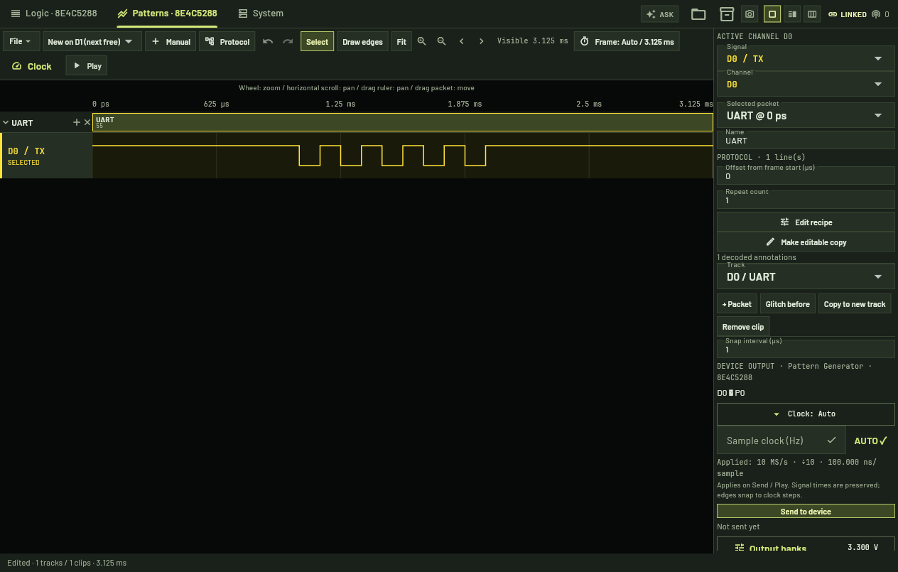
Control Hub pattern editing, output voltage settings and SPI loopback capture.
Patterns page: 4,096 vectors
Play fits the pattern into the hardware buffer by choosing a vector clock. If the recipe does not fit at its intended rate, playback uses a slower clock. Check the applied rate for timing-sensitive protocols; the default S/PDIF recipe exceeds this buffer at its true rate.
Long patterns through the driver/API
Shared capture memory supports up to 268 million vectors, depending on the memory split. Use the driver/API for patterns larger than the Patterns page buffer.
Synchronisation and electrical interface
The analyser can trigger on pattern start. The hardware also provides a pattern-start sync pulse and an external-edge start mode through the trigger connector.
Recipes generate logic-level waveforms. A bus may require a transceiver, level conversion or another interface circuit. Playing USB PD messages does not make the generator a PD source, sink or contract negotiator. PAM3 recipes for 10BASE-T1L and 100BASE-T1 require analog outputs and are not offered on the LA16 Patterns page.
04 / Features by layer
Software, firmware, gateware and hardware
Each feature belongs to one layer. Software, firmware and gateware are open source and every software feature is included on every device; hardware files follow the platform release policy.
Control Hub
Software
36 native decoders; 101 further protocols through the libsigrokdecode library integration.
LA16, scope- Capture analysis
Cursors, measurements, zoom and a 64-record capture history with trigger navigation.
LA16, scope 34 protocol recipes, clip editor and per-bank voltage settings for the Patterns page.
LA16USB PD, PoE, Modbus RTU and SPI flash analyzers combining instruments and test fixtures.
LA16 + fixturesDrivers for supported bench equipment over USB, Ethernet, RS-232 and GPIB.
Existing equipment- Network API
HTTP and WebSocket control of every widget, screenshots and a browser UI relay on one port.
All devices - Desktop, browser, tablet and remote access
One application; the shared touchscreen and remote browsers show the same session.
All devices - Assistant
Natural-language capture setup and decoding through the network API.
All devices
Instrument controller
Firmware
- Instrument command set
SCPI-style commands for acquisition, every trigger type, holdoff and pattern playback; settings are validated before arming.
LA16 - USB-C 3.0 and gigabit Ethernet transport
Bounded streaming buffers with counts and checksums; abort and re-arm.
LA16 - Host-loaded FPGA images
The driver selects the gateware image, including the protocol trigger images.
LA16 - Per-device calibration
Threshold slope and offset per input group and for the trigger input.
LA16 - Scope acquisition firmware
Acquisition modes, trigger coupling and hardware settings from the device descriptor.
Scope
FPGA
Gateware
- Capture engine
16 inputs into DDR sample memory with pre- and post-trigger allocation.
LA16 Seven trigger types with holdoff, evaluated at 700 MS/s before capture decimation.
LA16Frame, field and error conditions for CAN, CAN FD, serial buses, USB PD and other protocols.
LA16Up to four signal steps in the main image; one step arms the next.
LA16- External trigger input and output
Trigger-in to capture or generator start; trigger-out and generator-start pulses on the MCX connector.
LA16 4,096-vector page buffer plus long patterns streamed through the driver.
LA16- Scope acquisition
Four-channel 14-bit capture with the shared trigger interface.
Scope
Modules and rack
Hardware
Four threshold groups with independent references; 200 MHz input frontend.
LA16- 8 pattern outputs
Two drive-voltage groups, 1.65–3.3 V adjustable or 5 V.
LA16 - MCX trigger input / output
Independent threshold; does not consume a capture channel.
LA16 - USB-C 3.0 and 1G Ethernet
Host interfaces on every module; USB-C powered.
All modules Shared touchscreen and host computer as the base system.
Platform- Isolated measurement sides
Isolation barrier between measurement and host sides on the multimeter, power supply, load and SMU.
DMM, PSU, load, SMU
System architecture

05 / Open source & access
Open source and software access
All software features are available across all devices. Advanced analysis, protocol decoding and every trigger type the hardware supports are part of the system, with no paid software tiers or feature keys.
Read the source release policy ↗Software, firmware and gateware
Control Hub, controller firmware and FPGA gateware are open source.
Device compatibility
Use shared analysis wherever the captured data is compatible. Device-specific bandwidth, channel count and hardware trigger support are listed separately.
Source and licences
Source packages include their licence terms. The platform policy describes access to software and instrument hardware files.
Existing equipment
Control Hub connects to supported third-party instruments as well as Modular Bench hardware. Use the equipment already in your lab through the same application.
AI features
Set up decoders with a local model, describe custom sequences with Vibe Trigger, and control the bench through the AI assistant or an MCP-compatible client. Bring your own model and API key for the assistant.
Control Hub
Instrument software
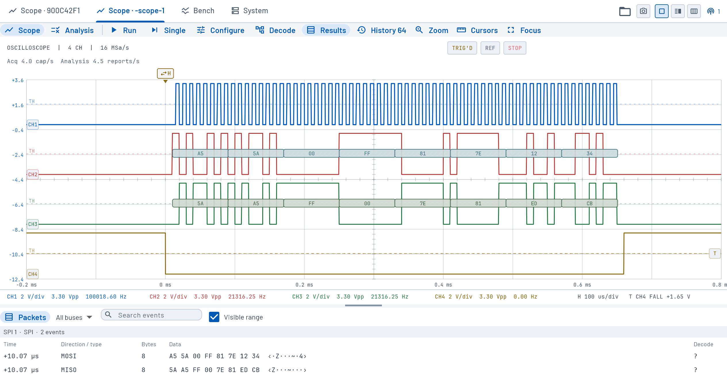
Four-channel waveform display with SPI decoding, packet results and channel controls.