Fixed and programmable power
Fixed, variable and battery profiles, PPS and SPR AVS. The bench emulator negotiates 5, 9, 15 or 20 V.
Control Hub bench
Debug USB PD charging and negotiation issues by watching messages and power together. Observe USB Power Delivery negotiations up to 48 V, including EPR. Decode messages alongside VBUS voltage, bus current and power. The source and sink negotiate the connection; the analyzer observes their exchange and cannot request or control a power contract.
Combine PD packet decoding with voltage and current measurements.
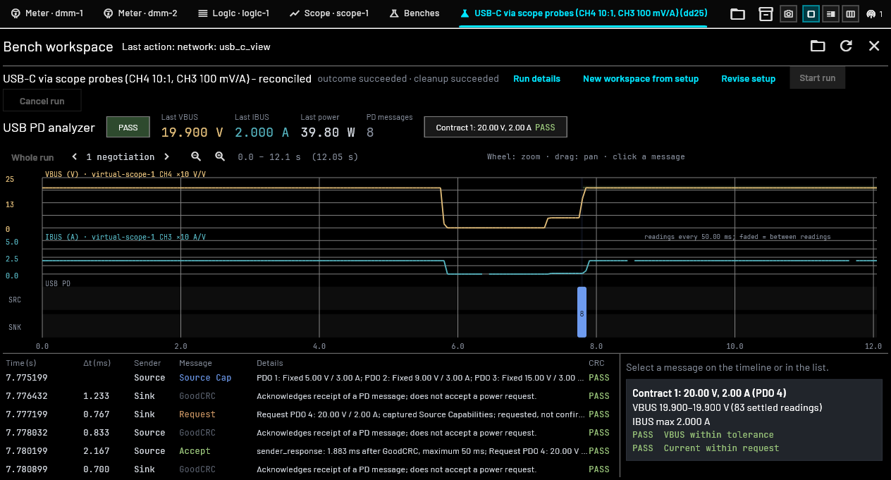 Control Hub · Emulated 20 V / 2 A run
To combine PD messages with measured voltage, current and power, use the USB PD Tap between the source and sink, plus a capture configuration below.
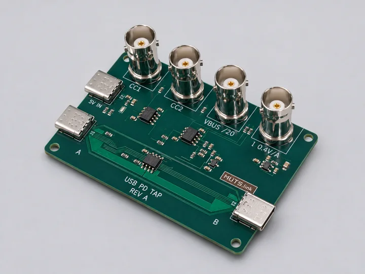
MB-EXP-0001 · Test fixture
$200.00 USD · Assembled tap board · 4 in stock · $29.99 USD worldwide shipping
Also works with an independent oscilloscope or multimeter, with no special software required for electrical measurements. Buffers both CC lines and provides scaled voltage/current outputs for observation up to 48 V. The tap does not negotiate, request a voltage, or decode traffic itself.
CC1 and CC2 use OPA2810 unity-gain buffers. Use 1 MΩ scope inputs. At 48 V, the VBUS ÷20 output is nominally 2.4 V. The tap requires one relative USB-C plug orientation and exposes only one cable’s E-marker.
The USB PD Tap with a single scope, or a scope or logic analyser with two multimeters. Select a configuration to see its connections and open it in the lab configurator. Fixtures and leads are selected separately.
Use the tap’s four BNC outputs for CC1, CC2, VBUS and current in one scope acquisition. Select the active CC channel for decoding; use high-impedance inputs.
The configurator selects instrument modules only. USB PD Tap, its power supply and connection leads are separate requirements.
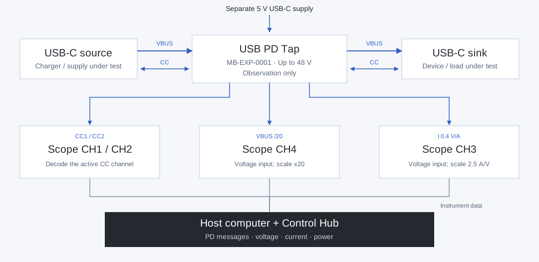
CH1 / CH2 · CC1 / CC2; decode active CC
CH4 · VBUS /20; scale ×20
CH3 · 0.4 V/A; scale 2.5 A/V
The tap provides scaled voltage outputs for VBUS and current. Use voltage inputs for both; do not connect the current-sense BNC to a DMM current socket. At 48 V VBUS, the nominal voltage output is 2.4 V.
Channels from one scope acquisition share a sample clock. Separate multimeter readings have their own sampling times; they do not provide scope-rate transient measurements.
Recorded in Control Hub: inspect source capabilities, a 20 V / 2 A request, Accept and PS_RDY alongside voltage and current. This demonstrates observing an emulated source/sink negotiation.
Negotiation and power measurements from the existing USB-C bench, plus an EPR request decoded in the scope view.
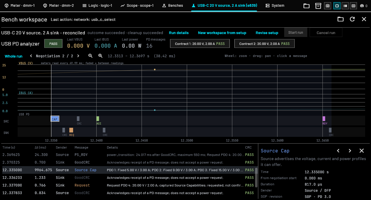
Control Hub example sessions with simulated instrument inputs. PASS labels refer to the configured run checks, not USB-IF certification.
The shared decoder covers PD 2.0 / 3.x messaging and supported PD 3.2 payloads. Raw data and packet-integrity results remain available alongside interpreted fields.
Fixed, variable and battery profiles, PPS and SPR AVS. The bench emulator negotiates 5, 9, 15 or 20 V.
Decode extended capabilities, AVS requests and EPR mode messages. EPR adds 28, 36 and 48 V profiles, up to 240 W in suitably rated systems.
USB-IF power-range reference ↗| Capability | Implemented software coverage |
|---|---|
| Packet decoding | BMC, SOP / SOP′ / SOP″, headers, raw payload, CRC-32, framing, hard reset and cable reset. |
| Power profiles | Fixed, variable and battery PDOs; PPS, SPR AVS and EPR AVS. RDO interpretation uses captured capability context or an embedded EPR PDO. |
| EPR messages | Observe extended capabilities, EPR requests, entry actions and keep-alive messages. Source and sink negotiate the contract; the analyzer does not transmit PD requests. |
| Negotiation | Source_Capabilities, Request, Accept, Reject, Wait, GoodCRC and PS_RDY. Requested, accepted and ready states remain distinct. |
| Cable and identity | Discover Identity, cable current/voltage capability, SVIDs, product identity and supported DisplayPort/Thunderbolt control fields. |
| Extended messages | Chunk reassembly, status, PPS status, battery information, alerts, supported authentication and firmware-update message schemas. |
The tap supports observation up to 48 V; the source, sink and cables must support the requested EPR contract. This is a PD analyzer, not a certified USB-IF compliance tester. USB 3.x/USB4 data traffic is outside this page’s scope.
Protocol messages and electrical measurements provide separate evidence. A requested voltage is not a measured VBUS value.
Inspect sender, message type, timestamps, inter-message delay, PDO/RDO fields, raw payload and CRC. Select a negotiation or review the complete run.
View VBUS and IBUS with contract targets and configured checks. Unconnected measurements remain marked as not measured.
Retain messages, power samples, CC captures and per-contract results. Probe scaling and input assignments are stored in the bench setup.
Scope voltage and current inputs can share the CC sample clock. Multimeter readings are timestamped separately and may be too slow to resolve a power-transition transient. Interpolation between readings does not add measurement bandwidth.
The shared decoder’s capture-local analysis and the bench’s continuous run analysis have different context boundaries. Gaps, resets and incomplete captures can prevent a negotiation conclusion. Decoded authentication or firmware-update messages do not authorize devices or perform updates.
USB PD analysis is included in the shared software. Software, firmware and gateware are open source; no decoder licence or feature unlock is required.