Oscilloscope on its own
See CC signaling, voltage transitions and load changes on any compatible scope. Use 1 MΩ voltage inputs; four channels show every output together. No special software required.
Test fixture · MB-EXP-0001
Debug charging, negotiation and runtime power
Debug USB PD charging issues with the test equipment you already own. Watch CC waveforms on an oscilloscope or measure runtime voltage and current with a multimeter. No special software required. Observe VBUS up to 48 V; add optional PD decoding to investigate negotiation messages.
SKU MB-EXP-0001
4 in stock · $29.99 USD worldwide shipping per order
Test checkout only — no real payment or shipment.
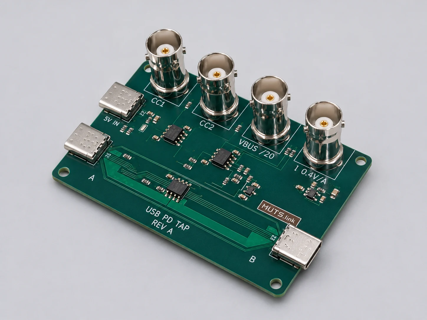
1 / 2Studio product view
USB PD Tap, Rev A. AI-retouched product photograph.
See CC signaling, voltage transitions and load changes on any compatible scope. Use 1 MΩ voltage inputs; four channels show every output together. No special software required.
Read bus voltage and current with a high-impedance meter in DC volts. Multiply VBUS /20 by 20 and I 0.4 V/A by 2.5 A/V. Use one meter in turn or two simultaneously.
To read negotiation messages, add a compatible scope decoder or Control Hub. A multimeter gives steady readings; a scope captures fast events.
Investigate a device that stays at 5 V, repeatedly reconnects or resets under load. Compare Source Capabilities, Request, Accept and PS_RDY with the measured VBUS transition to see where negotiation and delivered power diverge.
Observe the active CC line while the source and sink communicate. Decode messages with a compatible scope decoder or optional Control Hub software and inspect packet timing and integrity alongside the captured waveform, without asking the tap to negotiate a different contract.
Capture VBUS and current while the device starts, charges, sleeps or changes load. Compare those changes with PD messages in the same scope acquisition; calculate delivered power from the scaled voltage and current.
Optional: USB PD Tap + Oscilloscope + Control Hub
The Modular Bench brings PD messages and electrical measurements into one workflow. Capture both CC lines, bus voltage and current together, then follow a request through to the power transition or load event that explains the fault.
Explore the USB PD debugging bench ↗Oscilloscope specifications ↗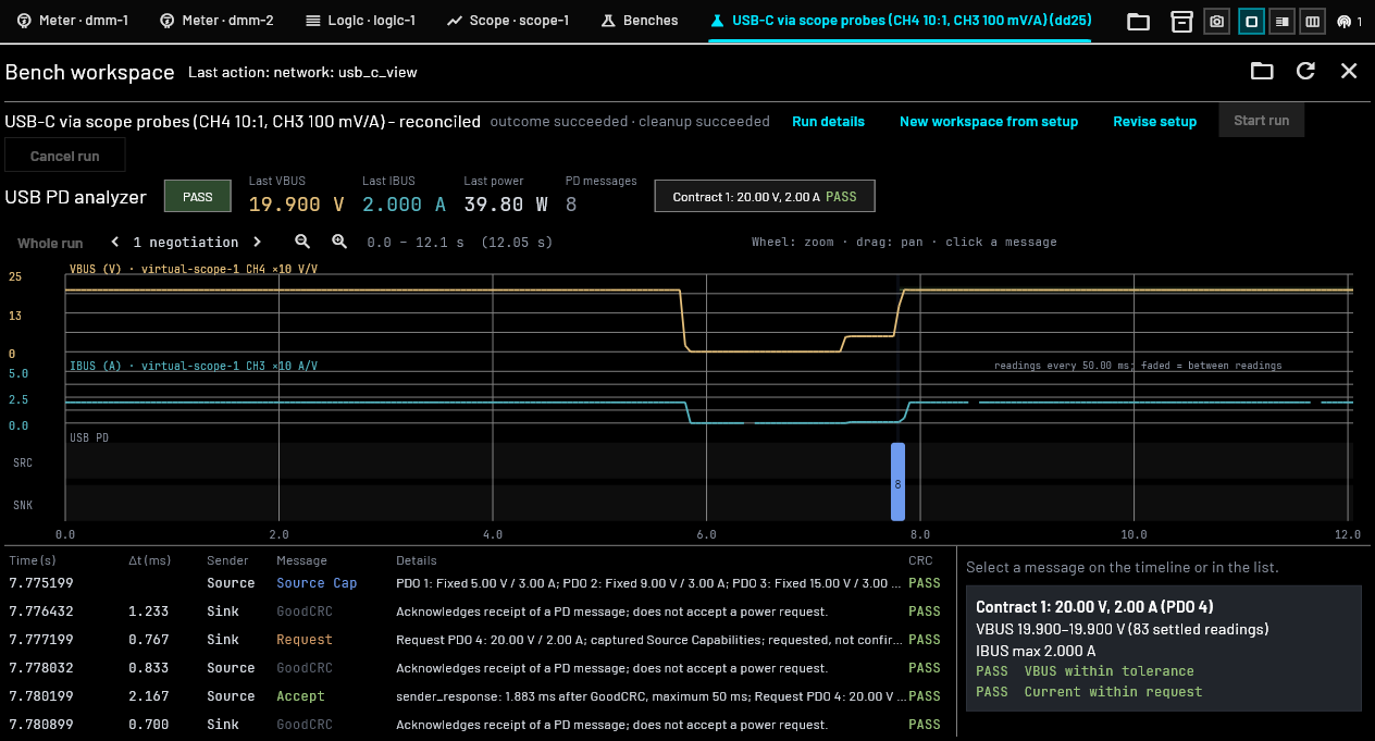
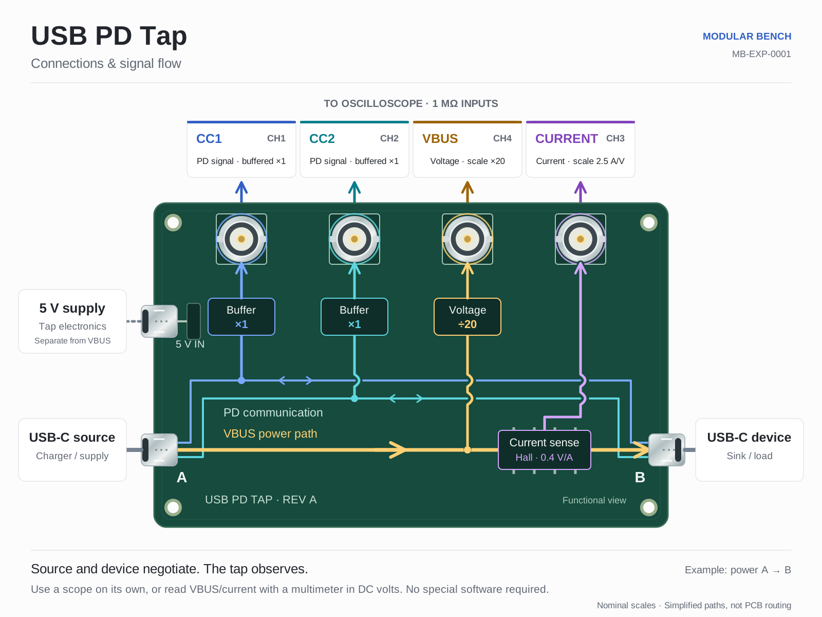
Insert USB-C ports A and B between the source and sink using suitable cables. Power 5 V IN from a separate 5 V USB-C supply. If the devices do not attach, reverse one plug to match the required relative orientation.
For steady bus voltage and current, use a high-impedance multimeter in DC volts on each scaled output in turn. For waveforms, connect CC1 to CH1, CC2 to CH2, the current output to CH3 and VBUS /20 to CH4 on a four-channel oscilloscope. Use 1 MΩ inputs and a compatible ground reference.
Set VBUS to ×20 and current to 2.5 A/V. Read the scaled values directly without software. For PD messages, optionally select the active CC channel in a compatible scope decoder or Control Hub. Inspect negotiation, voltage transitions and load changes together.
View the illustrated connection guide ↗
The $200.00 USD price is for the assembled USB PD Tap board. Add a separate 5 V supply, USB-C cables and measurement leads. Use your own oscilloscope or multimeter; no special software or computer is required for electrical measurements. Control Hub is optional for decoding and combined views.
Any compatible oscilloscope with 1 MΩ voltage inputs, or a high-impedance multimeter in DC volts for bus voltage and current readings. Four scope channels capture all outputs together; one meter reads voltage and current in turn, or two meters read both simultaneously.
Separate 5 V USB-C supply, two suitable USB-C cables for the pass-through path, and BNC measurement leads.
No special software or computer is needed for waveforms or meter readings. Use a compatible scope decoder or optional software such as Control Hub to decode PD messages. The tap requires no firmware or gateware.
| Parameter | Specification | Detail |
|---|---|---|
| Format | Standalone assembled board | External test fixture; no rack slot |
| USB PD role and range | Observation up to 48 V, including EPR | Source and sink negotiate; tap does not request or control a contract |
| PD observation | CC1 and CC2, nominal ×1 | OPA2810 unity-gain buffers; 49.9 Ω series output resistors |
| VBUS output | Nominal 50 mV/V (÷20) | 48 V VBUS gives 2.4 V at the output |
| Current output | Nominal 0.4 V/A | Voltage output; zero-centred, positive A to B |
| Measurement input | High-impedance voltage input | 1 MΩ oscilloscope or high-impedance multimeter in DC volts |
| Fixture supply | Separate 5 V USB-C input | Independent of the bus under test |
Yes. Use any compatible oscilloscope with 1 MΩ voltage inputs or a high-impedance multimeter in DC volts. No Modular Bench hardware, Control Hub software or computer is required for electrical measurements. Supply separate 5 V power and suitable leads, and check ground-reference compatibility. PD message decoding is optional and requires a compatible decoder.
Place the USB PD Tap between the USB-C source and sink, power its separate 5 V input, and connect CC1 and CC2 to high-impedance oscilloscope inputs. A scope displays the waveforms on its own. To read messages, select the active CC channel in a compatible scope decoder or optional software such as Control Hub. The tap exposes signals and does not decode them itself.
Connect VBUS /20 and I 0.4 V/A to oscilloscope voltage inputs set to 1 MΩ, or a high-impedance multimeter set to DC volts. Use one meter in turn or two simultaneously. No special software is required. Never use the meter current socket for these voltage outputs. Multiply the VBUS output by 20 and the current output by 2.5 A/V. For example, 1 V at VBUS /20 represents 20 V on the bus, and 0.8 V at the current output represents 2 A. These are nominal scale examples, not accuracy specifications. Current is positive from A to B.
Capture the active CC line and VBUS together. Check the advertised Source Capabilities, the sink Request, the source response and PS_RDY, then compare their timing with VBUS. This helps distinguish a missing request, a rejected contract and a power transition that does not complete. The tap observes the exchange; it cannot force a higher voltage.
The tap provides access to CC1, CC2, VBUS and current. A four-channel oscilloscope captures all four outputs together, and Control Hub combines PD decoding with voltage, current and power views. This makes the setup useful when you need to explain a charging fault or reset using both messages and electrical behavior.
The tap supports observation up to 48 V, including EPR source/sink negotiations. At 48 V, its VBUS /20 output is nominally 2.4 V. Use suitable source, sink and cables. It does not negotiate EPR or certify a system for USB-IF compliance.
It works independently of the Modular Bench and Control Hub with a separate 5 V supply, leads and a compatible oscilloscope or multimeter. No special software is required for electrical measurements. Reading PD messages requires an optional decoder; a multimeter cannot decode traffic. Its BNC outputs expose PD signaling on CC1/CC2 and bus voltage/current; they do not capture USB payload data. The tap cannot send PD requests or force a contract.
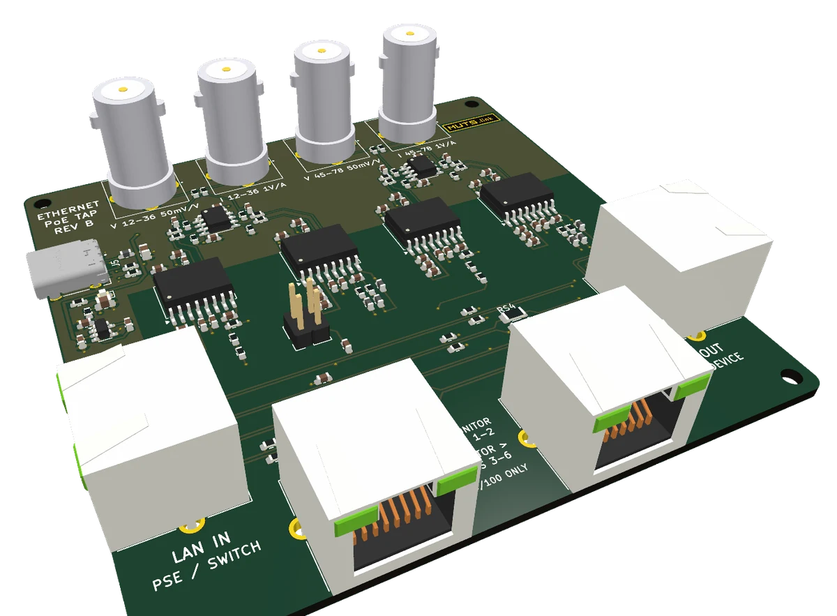
MB-EXP-0002
MB-EXP-0003