Network equipment
The Ethernet source and device under test, patch cables and compatible receive interfaces for packet capture.
Test fixture · MB-EXP-0002
Insert between an Ethernet power source and device to access receive-only network monitor ports and separate PoE voltage and current outputs.
SKU MB-EXP-0002
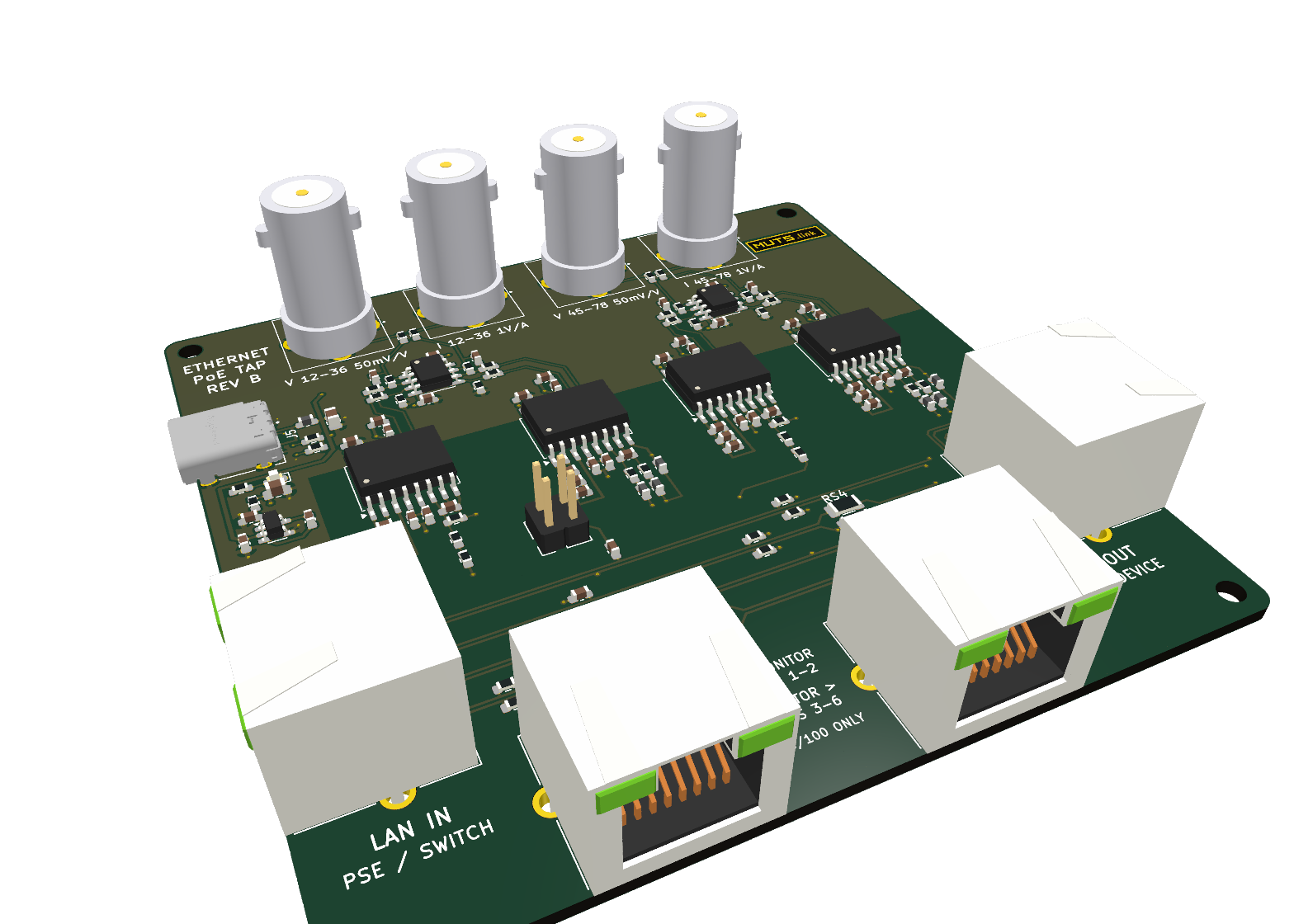
LAN pass-through, two 10/100 monitor ports and four PoE measurement outputs.
The Ethernet source and device under test, patch cables and compatible receive interfaces for packet capture.
Use one oscilloscope for the PoE power analyzer bench: one voltage channel minimum, or four channels for voltage and current on both pair groups. Voltage meters can read individual tap outputs separately.
Use compatible monitor interfaces and a common measurement reference. Power the fixture separately from its USB-C input.
| Parameter | Specification | Detail |
|---|---|---|
| Format | Standalone assembled board | External test fixture; no rack slot |
| Ethernet path | LAN IN to LAN OUT | Pass-through connection |
| Monitor ports | Two receive-only ports; 10/100 only | 10/100 packet observation |
| PoE observation | Pair groups 1–2 / 3–6 and 4–5 / 7–8 | Separate voltage and current outputs |
| Voltage outputs | Nominal 50 mV/V | High-impedance voltage measurement |
| Current outputs | Nominal 1 V/A | Voltage signals for measurement inputs |
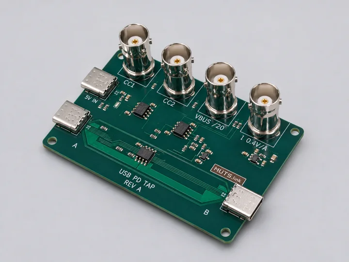
MB-EXP-0001
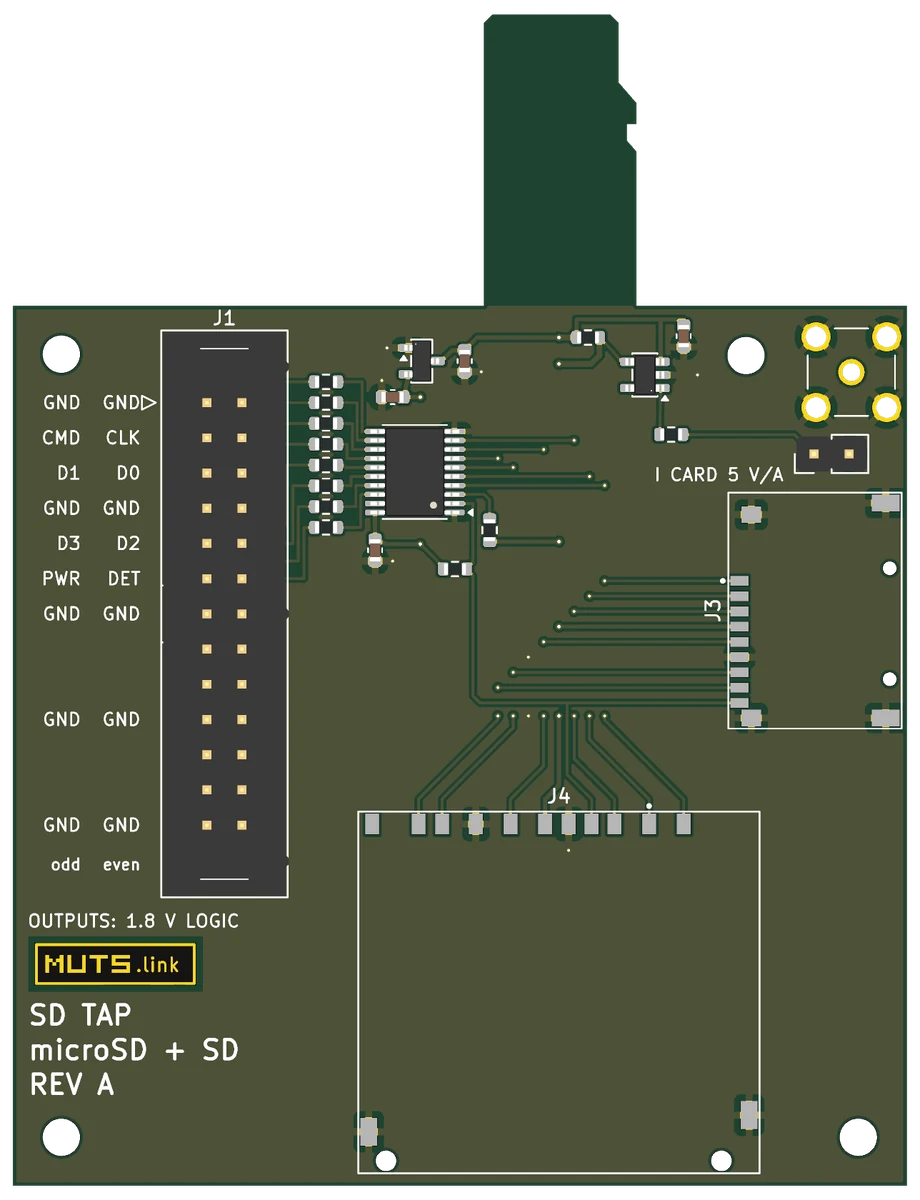
MB-EXP-0003