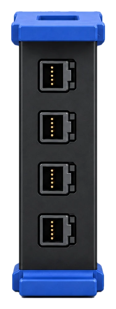
Logic Analyser
MB-LA16
Instrument module · MB-LOAD
DC electronic load in the same enclosure and front-panel layout as the power supply. Use constant-current, constant-voltage, constant-resistance or constant-power operation to exercise a supply or battery.
SKU MB-LOAD
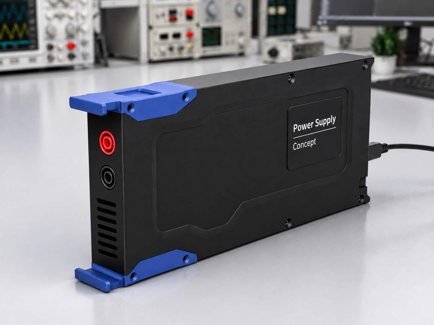
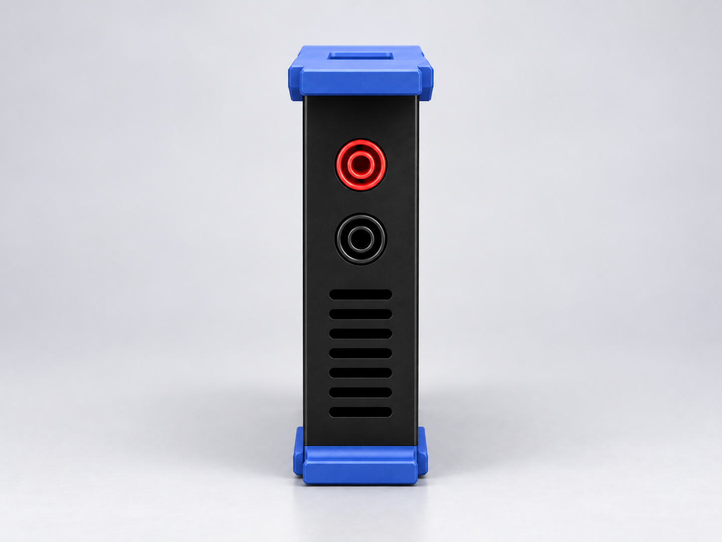
1 / 2Bench view (shared enclosure)
Block diagram
The input terminals pass through fused, reverse-polarity protection to a power MOSFET sink stage with voltage and current sense on the isolated load side. Control and readings cross the isolation barrier to the MCU, which presents the module over USB-C 3.0 and gigabit Ethernet.
BLOCK-LEVEL · NOT A SCHEMATIC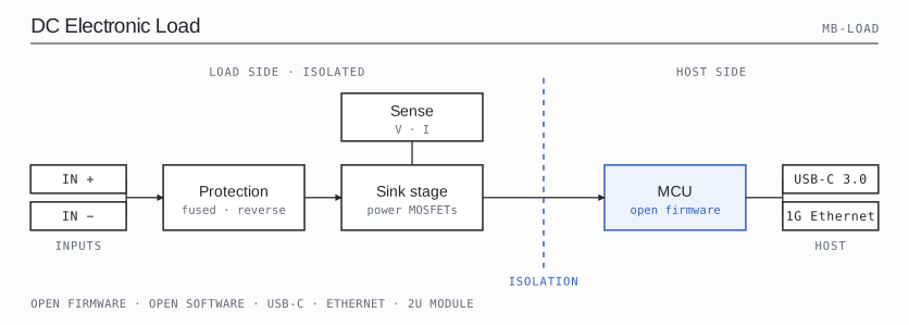
Specifications and connections for the dc electronic load.
| Parameter | Specification | Detail |
|---|---|---|
| Operating modes | CC · CV · CR · CP | |
| Input terminals | Shares the power supply front panel | Shared power supply enclosure |
| Parameter | Specification | Detail |
|---|---|---|
| Module format | 2U | Modular Bench format |
| Rack capacity | 7 module positions | Modular Bench format |
| User interface | Shared touchscreen | Modular Bench format |
| Control interfaces | USB-C / Ethernet | Modular Bench format |
| Power input | USB-C | Modular Bench format |
MB-LA16
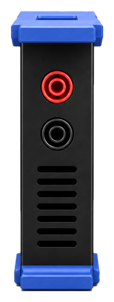
MB-PS240
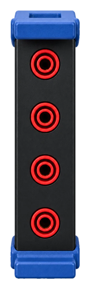
MB-DMM45
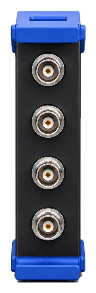
MB-SCOPE14
MB-AWG4
MB-SMU